Hierarchical Network Models – Enterprise LAN Design and Technologies

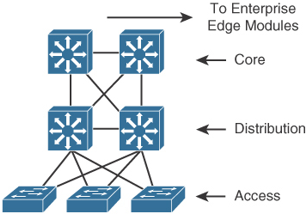
Hierarchical models enable you to design internetworks that use specialization of function combined with a hierarchical organization. Such a design simplifies the tasks required to build a network that meets current requirements and that can grow to meet future requirements. Hierarchical models use layers to simplify the tasks for internetworking. Each layer can focus on specific functions, allowing you to choose the right systems and features for each layer. Hierarchical models apply to both LAN and WAN design.

Benefits of the Hierarchical Model

The benefits of using hierarchical models for your network design include the following:

  • Cost savings
  • Ease of understanding
  • Modular network growth
  • Improved fault isolation

After adopting hierarchical design models, many organizations report cost savings because they are no longer trying to do everything in one routing or switching platform. The modular nature of such a model enables appropriate use of bandwidth within each layer of the hierarchy, reducing the provisioning of bandwidth in advance of actual need.

Keeping each design element simple and functionally focused facilitates ease of understanding, which helps control training and staff costs. You can distribute network monitoring and management reporting systems to the different layers of modular network architectures, which also helps control management costs.

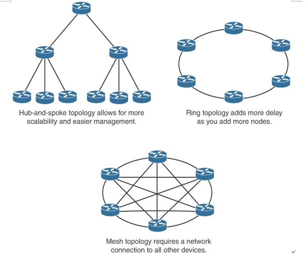
Hierarchical design facilitates changes and growth. In a network design, modularity lets you create design elements that you can replicate as the network grows—allowing maximum scalability. Because each element in the network design requires change, the cost and complexity of making the upgrade are contained to a small subset of the overall network. In large, flat network architectures, changes tend to impact a large number of systems. Limited mesh topologies within a layer or component, such as the campus core or backbone connecting central sites, retain value even in the hierarchical design models.

Structuring the network into small, easy-to-understand elements improves fault isolation. Network managers can easily understand the transition points in the network, which helps identify failure points. A network without hierarchical design is more difficult to troubleshoot because the network is not divided into segments.

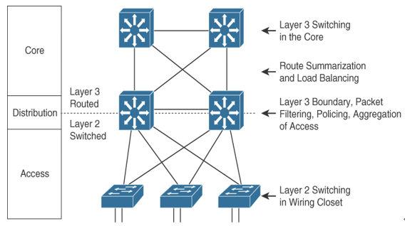
Today’s fast-converging protocols were designed for hierarchical topologies. To control the impact of routing-protocol processing and bandwidth consumption, you must use modular hierarchical topologies with protocols designed with these controls in mind, such as the Open Shortest Path First (OSPF) routing protocol.

Hierarchical network design facilitates route summarization. Enhanced Interior Gateway Routing Protocol (EIGRP) and all other routing protocols benefit greatly from route summarization. Route summarization reduces routing-protocol overhead on links in the network and reduces routing-protocol processing within the routers. It is less possible to provide route summarization if the network is not hierarchical.

Hierarchical Network Design – Enterprise LAN Design and Technologies

As shown in Figure 6-1, a traditional hierarchical LAN design has three layers:

Figure 6-1 Hierarchical Network Design Has Three Layers: Core, Distribution, and Access 

  • Core: The core layer provides fast transport between distribution switches within the enterprise campus.
  • Distribution: The distribution layer provides policy-based connectivity.
  • Access: The access layer provides workgroup and user access to the network.

Each layer provides necessary functionality to the enterprise campus network. You do not need to implement the layers as distinct physical entities. You can implement each layer in one or more devices or as cooperating interface components sharing a common chassis. Smaller networks can “collapse” multiple layers to a single device with only an implied hierarchy. Maintaining an explicit awareness of hierarchy is useful as the network grows.

Core Layer

The core layer is the network’s high-speed switching backbone and is crucial to corporate communications. It is also referred to as the backbone. The core layer should have the following characteristics:

  • Fast transport
  • High reliability
  • Redundancy
  • Fault tolerance
  • Low latency and good manageability
  • Avoidance of CPU-intensive packet manipulation caused by security, inspection, quality-of-service (QoS) classification, or other processes
  • Limited and consistent diameter
  • QoS

When a network uses routers, the number of router hops from edge to edge is called the diameter. As noted, it is considered good practice to design for a consistent diameter within a hierarchical network. The trip from any end station to another end station across the backbone should have the same number of hops. The distance from any end station to a server on the backbone should also be consistent.

Limiting the internetwork’s diameter provides predictable performance and ease of troubleshooting. You can add distribution layer routers and client LANs to the hierarchical model without increasing the core layer’s diameter. Use of a block implementation isolates existing end stations from most effects of network growth.

Distribution Layer

The network’s distribution layer is the isolation point between the network’s access and core layers. The distribution layer can have many roles, including implementing the following functions:

  • Policy-based connectivity (for example, ensuring that traffic sent from a particular network is forwarded out one interface while all other traffic is forwarded out another interface)
  • Redundancy and load balancing
  • Aggregation of LAN wiring closets
  • Aggregation of WAN connections
  • QoS
  • Security filtering
  • Address or area aggregation or summarization
  • Departmental or workgroup access
  • Broadcast or multicast domain definition
  • Routing between virtual local-area networks (VLANs)
  • Media translations (for example, between Ethernet and Token Ring)
  • Redistribution between routing domains (for example, between two different routing protocols)
  • Demarcation between static and dynamic routing protocols

You can use several Cisco IOS software features to implement policy at the distribution layer:

  • Filtering by source or destination address
  • Filtering on input or output ports
  • Hiding internal network numbers through route filtering
  • Static routing
  • QoS mechanisms, such as priority-based queuing

The distribution layer performs aggregation of routes providing route summarization to the core. In the campus LANs, the distribution layer provides routing between VLANs that also apply security and QoS policies.

Access Layer – Enterprise LAN Design and Technologies

The access layer provides user access to local segments on the network. The access layer is characterized by switched LAN segments in a campus environment. Microsegmentation using LAN switches provides high bandwidth to workgroups by reducing the number of devices on Ethernet segments. Functions of the access layer include the following:

  • Layer 2 switching
  • High availability
  • Port security
  • Broadcast suppression
  • QoS classification and marking and trust boundaries
  • Rate limiting/policing
  • Address Resolution Protocol (ARP) inspection
  • Virtual access control lists (VACLs)
  • Spanning tree
  • Trust classification
  • Power over Ethernet (PoE) and auxiliary VLANs for VoIP
  • Network access control (NAC)
  • Auxiliary VLANs

Table 6-2 summarizes the hierarchical layer functions.

Table 6-2 Cisco Hierarchical Layer Functions

Hierarchical LayerLayer Functions
CoreFast transport
 High reliability
 Redundancy
 Fault tolerance
 Low latency and good manageability
 Avoidance of slow packet manipulation caused by filters or other processes
 Limited and consistent diameter
 QoS
DistributionPolicy-based connectivity
 Redundancy and load balancing
 Aggregation of LAN wiring closets
 Aggregation of WAN connections
 QoS
 Security filtering
 Address or area aggregation or summarization
 Departmental or workgroup access
 Broadcast or multicast domain definition
 Routing between VLANs
 Media translations (for example, between Ethernet and Token Ring)
 Redistribution between routing domains (for example, between two different routing protocols)
 Demarcation between static and dynamic routing protocols
AccessLayer 2 switching
 High availability
 Port security
 Broadcast suppression
 QoS
 Rate limiting
 ARP inspection
 VACLs
 Spanning tree
 Trust classification
 Network access control (NAC)
 PoE and auxiliary VLANs for VoIP

Hierarchical Model Examples

You can implement the hierarchical model by using a traditional switched campus design or routed campus network. Figure 6-2 is an example of a switched hierarchical design in the enterprise campus. In this design, the core provides high-speed transport between the distribution layers. The building distribution layer provides redundancy and allows policies to be applied to the building access layer. Layer 3 links between the core and distribution switches are recommended to allow the routing protocol to take care of load balancing and fast route redundancy in the event of a link failure.

Figure 6-2 Switched Hierarchical Design

The distribution layer is the boundary between the Layer 2 domains and the Layer 3 routed network. Inter-VLAN communications are routed in the distribution layer. Route summarization is configured under the routing protocol on interfaces toward the core layer. The drawback with this design is that Spanning Tree Protocol allows only one of the redundant links between the access switch and the distribution switch to be active. In the event of a failure, the second link becomes active, but at no point does load balancing occur.

Figure 6-3 shows examples of a routed hierarchical design. In this design, the Layer 3 boundary is pushed toward the access layer. Layer 3 switching occurs in the access, distribution, and core layers. Route filtering is configured on interfaces toward the access layer. Route summarization is configured on interfaces toward the core layer. The benefit of this design is that load balancing occurs from the access layer because the links to the distribution switches are routed.

Figure 6-3 Routed Hierarchical Design

VSS

One solution for providing redundancy between the access and distribution switching is Virtual Switching System (VSS). VSS solves the Spanning Tree Protocol looping problem by converting the distribution switching pair into a logical single switch. It removes Spanning Tree Protocol and eliminates the need for Hot Standby Router Protocol (HSRP), Virtual Router Redundancy Protocol (VRRP), or Gateway Load Balancing Protocol (GLBP).

With VSS, the physical topology changes as each access switch has a single upstream distribution switch rather than two upstream distribution switches. As shown in Figure 6-4, the two switches are connected via 10 Gigabit Ethernet links called virtual switch links (VSLs), which makes them seem as a single switch. The key benefits of VSS include the following:

Figure 6-4 VSS

  • Layer 3 switching used toward the access layer to enhance nonstop communication
  • Simplified management of a single configuration of the VSS distribution switch
  • Better return on investment (ROI) thanks to increased bandwidth between the access layer and the distribution layer
  • Multichassis EtherChannel (MEC) creating loop-free technologies and eliminating the need for Spanning Tree Protocol

Hub-and-Spoke Design – Enterprise LAN Design and Technologies

The hub-and-spoke network design (see Figure 6-5) provides better convergence times than ring topology. The hub-and-spoke design also scales better and is easier to manage than ring or mesh topologies. For example, implementing security policies in a full-mesh topology would become unmanageable because you would have to configure policies at each point location. Using the formula n(n − 1)/2, a mesh of 6 devices would generate 6 (6 − 1)/2 = 30/2 = 15 links.

Figure 6-5 Hub-and-Spoke Versus Ring and Mesh Designs

Collapsed Core Design

One alternative to the three-layer hierarchy is the collapsed core design, which is a two-layer hierarchy used with smaller networks. It is commonly used in sites with a single building with multiple floors. As shown in Figure 6-6, the core and distribution layers are merged, providing all the services needed for those layers. Design parameters to decide if you need to migrate to the three-layer hierarchy include not enough capacity and throughput at the distribution layer, network resiliency, and geographic dispersion.

Figure 6-6 Collapsed Core Design

Building Triangles and Redundant Links

A common thread that you will see in Cisco design is building redundant triangles rather than building squares. When you build in triangles, you take advantage of equal-cost redundant paths for best deterministic convergence. In the networks shown in Figure 6-7, when the link at location A goes down, the design with triangles does not require routing protocol convergence because each switch has two routes and two associated hardware Cisco Express Forwarding adjacency entries. In the design with squares, routing convergence is required.

Figure 6-7 Building Triangles

When you are designing a hierarchical campus, using redundant links with triangles enables equal-cost path routing. In equal-path cost design, each switch has two routes and two Cisco Express Forwarding adjacency entries. This design allows for the fastest restoration of voice, video, and data traffic flows. As shown in Figure 6-8, there are two Cisco Express Forwarding entries in the initial state. When a switch failure occurs, the originating switch still has a remaining route and associated Cisco Express Forwarding entry; because of this, it does not trigger or wait for routing protocol convergence and is immediately able to continue forwarding all traffic.

Figure 6-8 Redundant Links

Local Versus End-to-End VLAN Design Models

In the enterprise campus, you could deploy VLANs across the campus or contain VLANs within the physical location. The term end-to-end VLANs refers to the design that allows VLANs to be widely dispersed throughout the enterprise network. The advantage of this design is that a user can move from one building to another and remain in the same VLAN. The problem is that this design does not scale well for thousands of users, which makes it difficult to manage.

The recommended solution is to implement local VLANs where users are grouped into VLANs based on their physical locations. A Layer 2 to Layer 3 demarcation is created at the distribution layer, providing the ability to apply distribution layer summaries, QoS, segmentation, and other features. Furthermore, local VLANs decrease convergence times, and traffic flow is predictable, which makes troubleshooting easier. Figure 6-9 shows local VLANs versus end-to-end VLANs.

Figure 6-9 Local VLANs Versus End-to-End VLANs

LAN Media – Enterprise LAN Design and Technologies

This section identifies some of the constraints you should consider when provisioning various LAN media types. It covers the physical specifications of Ethernet, Fast Ethernet, and Gigabit Ethernet.

Ethernet Design Rules

Ethernet is the underlying basis for the technologies most widely used in LANs. In the 1980s and early 1990s, most networks used 10 Mbps Ethernet, defined initially by Digital, Intel, and Xerox (DIX Ethernet Version II) and later by the IEEE 802.3 working group. The IEEE 802.3-2002 standard contains physical specifications for Ethernet technologies through 10 Gbps.

100 Mbps Fast Ethernet Design Rules

The IEEE introduced the IEEE 802.3u-1995 standard to provide Ethernet speeds of 100 Mbps over UTP and fiber cabling. The 100BASE-T standard is similar to 10 Mbps Ethernet in that it uses Carrier Sense Multiple Access/Collision Detect (CSMA/CD); runs on Category (CAT) 3, 4, 5, and 6 UTP cable; and preserves the frame formats.

The 100 Mbps Ethernet (or Fast Ethernet) topologies present some distinct constraints on the network design because of their speed. The combined latency due to cable lengths and repeaters must conform to the specifications for the network to work properly. This section discusses these issues and provides sample calculations.

The overriding design rule for 100 Mbps Ethernet networks is that the round-trip collision delay must not exceed 512-bit times. However, the bit time on a 100 Mbps Ethernet network is 0.01 microseconds, as opposed to 0.1 microseconds on a 10 Mbps Ethernet network. Therefore, the maximum round-trip delay for a 100 Mbps Ethernet network is 5.12 microseconds, as opposed to the more lenient 51.2 microseconds in a 10 Mbps Ethernet network.

The following are specifications for Fast Ethernet, which are described in the following sections:

  • 100BASE-TX
  • 100BASE-T4
  • 100BASE-FX
100BASE-TX Fast Ethernet

The 100BASE-TX specification uses CAT 5 or 6 UTP wiring. Fast Ethernet uses only two pairs of the four-pair UTP wiring. The specifications are as follows:

  • Transmission occurs over CAT 5 or 6 UTP wire.
  • RJ-45 connectors are used (the same as in 10BASE-T).
  • Punchdown blocks in the wiring closet must be CAT 5 certified.
  • 4B5B coding is used.
100BASE-T4 Fast Ethernet

The 100BASE-T4 specification was developed to support UTP wiring at the CAT 3 level. This specification takes advantage of higher-speed Ethernet without recabling to CAT 5 UTP. This implementation is not widely deployed. The specifications are as follows:

  • Transmission occurs over CAT 3, 4, 5, or 6 UTP wiring.
  • Three pairs are used for transmission, and the fourth pair is used for collision detection.
  • No separate transmit and receive pairs are present, so full-duplex operation is not possible.
  • 8B6T coding is used.
100BASE-FX Fast Ethernet

The 100BASE-FX specification for fiber is as follows:

  • It operates over two strands of multimode or single-mode fiber cabling.
  • It can transmit over greater distances than copper media.
  • It uses media interface connector (MIC), stab and twist (ST), or stab and click (SC) fiber connectors defined for FDDI and 10BASE-FX networks.
  • 4B5B coding is used.

Gigabit Ethernet Design Rules – Enterprise LAN Design and Technologies

Gigabit Ethernet was first specified by two standards: IEEE 802.3z-1998 and 802.3ab-1999. The IEEE 802.3z standard specifies the operation of Gigabit Ethernet over fiber and coaxial cable and introduced the Gigabit Media-Independent Interface (GMII). These standards have been superseded by the latest revision of all the 802.3 standards included in IEEE 802.3-2002.

The IEEE 802.3ab standard specified the operation of Gigabit Ethernet over CAT 5 UTP. Gigabit Ethernet still retains the frame formats and frame sizes, and it still uses CSMA/CD. As with Ethernet and Fast Ethernet, full-duplex operation is possible. Differences appear in the encoding; Gigabit Ethernet uses 8B10B coding with simple nonreturn to zero (NRZ). Because of the 20% overhead, pulses run at 1250 MHz to achieve 1000 Mbps throughput.

Table 6-3 provides an overview of Gigabit Ethernet scalability constraints.

Table 6-3 Gigabit Ethernet Scalability Constraints

TypeSpeedMaximum Segment LengthEncodingMedia
1000BASE-T1000 Mbps100 mFive-levelCAT 5 UTP
1000BASE-LX (long wavelength)1000 Mbps550 m8B10BSingle-mode/multimode fiber
1000BASE-SX (short wavelength)1000 Mbps62.5 micrometers: 220 m 50 micrometers: 500 m8B10BMultimode fiber
1000BASE-CX1000 Mbps25 m8B10BShielded balanced copper

The following are the physical specifications for Gigabit Ethernet, which are described in the following sections:

  • 1000BASE-LX
  • 1000BASE-SX
  • 1000BASE-CX
  • 1000BASE-T
1000BASE-LX Long-Wavelength Gigabit Ethernet

IEEE 1000BASE-LX uses long-wavelength optics over a pair of fiber strands. The specifications are as follows:

  • It uses long wavelengths (1300 nm [nanometers]).
  • It can be used on multimode or single-mode fiber.
  • Maximum lengths for multimode fiber are as follows:
    • 62.5-micrometer fiber: 440 meters
    • 50-micrometer fiber: 550 meters
  • The maximum length for single-mode fiber (9 micrometers) is 5 km.
  • It uses 8B10B encoding with simple NRZ.
1000BASE-SX Short-Wavelength Gigabit Ethernet

IEEE 1000BASE-SX uses short-wavelength optics over a pair of multimode fiber strands. The specifications are as follows:

  • It uses short wavelengths (850 nm).
  • It can be used on multimode fiber.
  • Maximum lengths are as follows:
    • 62.5-micrometer fiber: 260 m
    • 50-micrometer fiber: 550 m
  • It uses 8B10B encoding with simple NRZ.
1000BASE-CX Gigabit Ethernet over Coaxial Cable

The IEEE 1000BASE-CX standard is for short copper runs between servers. The specifications are as follows:

  • It is used on short-run copper.
  • It runs over a pair of 150-ohm balanced coaxial cables (twinax).
  • The maximum length is 25 meters.
  • It is mainly for server connections.
  • It uses 8B10B encoding with simple NRZ.
1000BASE-T Gigabit Ethernet over UTP

The IEEE standard for 1000 Mbps Ethernet over CAT 5 UTP was IEEE 802.3ab; it was approved in June 1999. It is now included in IEEE 802.3-2002. This standard uses the four pairs in the cable. (100BASE-TX and 10BASE-T Ethernet use only two pairs.) The specifications are as follows:

  • It uses CAT 5 four-pair UTP.
  • The maximum length is 100 meters.
  • The encoding defined is a five-level coding scheme.
  • One byte is sent over the four pairs at 1250 MHz.

10 Gigabit Ethernet Design Rules – Enterprise LAN Design and Technologies

The IEEE 802.3ae supplement to the 802.3 standard, published in August 2002, specifies the standard for 10 Gigabit Ethernet. It is defined for full-duplex operation over optical media, UTP, and copper. The IEEE 802.3an standard provides the specifications for running 10 Gigabit Ethernet over UTP cabling. Hubs or repeaters cannot be used because they operate in half-duplex mode. It allows the use of Ethernet frames over distances typically encountered in metropolitan-area networks (MANs) and wide-area networks (WANs). Other uses include data centers, corporate backbones, and server farms.

10 Gigabit Ethernet Media Types

10 Gigabit Ethernet has seven physical media specifications, based on different fiber types and encodings. Multimode fiber (MMF) and single-mode fiber (SMF) are used. Table 6-4 describes the different 10 Gigabit Ethernet media types.

Table 6-4 10 Gigabit Ethernet Media Types

Media TypeWavelength and Fiber/UTP/CopperDistanceOther Description
10GBASE-SRShort-wavelength MMFTo 300 mUses 66B encoding
10GBASE-SWShort-wavelength MMFTo 300 mUses the WAN interface sublayer (WIS)
10GBASE-LRLong-wavelength SMFTo 10 kmUses 66B encoding for dark fiber use
10GBASE-LWLong-wavelength SMFTo 10 kmUses WIS
10GBASE-ERExtra-long-wavelength SMFTo 40 kmUses 66B encoding for dark fiber use
10GBASE-EWExtra-long-wavelength SNMPTo 40 kmUses WIS
10GBASE-LX4Uses division multiplexing for both MMF and SMFTo 10 kmUses 8B/10B encoding
10GBASE-CX4Four pairs of twinax copper15 mIEEE 802.3ak
10GBASE-TCAT 6a UTP100 mIEEE 802.3an
10GBASE-ZRLong-wave SMF80 kmNot in 802.3ae
10GBASE-PRPassive optical network20 km10G EPON 802.3av

Short-wavelength multimode fiber is 850 nm. Long-wavelength is 1310 nm, and extra-long-wavelength is 1550 nm. The WIS is used to interoperate with Synchronous Optical Network (SONET) STS-192c transmission format.

IEEE 802.3ba is the designation given for the 802.3 standard, and speeds higher than 10 Gbps are paving the way for 40 Gbps and 100 Gbps Ethernet. Both 40 Gigabit Ethernet and 100 Gigabit Ethernet have emerged as backbone technologies for networks. Table 6-5 describes some of the physical standards.

Table 6-5 40 Gigabit Ethernet and 100 Gigabit Ethernet Physical Standards

Physical Layer40 Gigabit Ethernet100 Gigabit Ethernet
Backplane100GBASE-KP4
Improved backplane40GBASE-KR4100GBASE-KR4
7 m over twinax copper cable40GBASE-CR4100GBASE-CR10 100GBASE-CR4
30 m over Cat.8 UTP40GBASE-T
100 m over OM3 MMF 125 m over OM4 MMF40GBASE-SR4100GBASE-SR10 100GBASE-SR4
2 km over SMF40GBASE-FR100GBASE-CWDM4
10 km over SMF40GBASE-LR4100GBASE-LR4
40 km over SMF40GBASE-ER4100GBASE-ER4

EtherChannel – Enterprise LAN Design and Technologies

The Cisco EtherChannel implementations provide a method to increase the bandwidth between two systems by bundling Fast Ethernet, Gigabit Ethernet, or 10 Gigabit Ethernet links. When bundling Fast Ethernet links, use Fast EtherChannel. Gigabit EtherChannel bundles Gigabit Ethernet links. EtherChannel port bundles enable you to group multiple ports into a single logical transmission path between a switch and a router, a switch and a host, or a switch and another switch. EtherChannels provide increased bandwidth, load sharing, and redundancy. If a link in the bundle fails, the other links take on the traffic load. You can configure EtherChannel bundles as trunk links.

Depending on your hardware, you can form an EtherChannel with up to eight compatibly configured ports on the switch. The participating ports in an EtherChannel trunk must have the same speed and duplex mode and belong to the same VLAN. Cisco’s proprietary hash algorithm calculates the way load balancing occurs, as shown in Table 6-6.

Table 6-6 EtherChannel Load Balancing

Number of Ports in EtherChannelLoad Balancing Between Ports
81:1:1:1:1:1:1:1
72:1:1:1:1:1:1
62:2:1:1:1:1
52:2:2:1:1
42:2:2:2
33:3:2
24:4
Port Aggregation Considerations

When EtherChannel is configured to bundle Layer 2 links, it aggregates the bandwidth of these links and changes Spanning Tree Protocol behavior because all links are treated as one link and thus are all in the Spanning Tree Protocol forwarding state.

When EtherChannel is configured for Layer 3 links, it aggregates the bandwidth of multiple Layer 3 links and optimizes routing because there is only one neighbor relationship per switch interconnection.

EtherChannel can be established by using three mechanisms:

  • LACP: Link Aggregation Control Protocol (LACP) is defined in IEEE 802.3ad. It protects against misconfiguration but adds overhead and delay when setting up a bundle.
  • PAgP: Port Aggregation Protocol (PAgP) is a Cisco-proprietary negation protocol. PAgP aids in the automatic creation of EtherChannel links.
  • Static persistence configuration: This configuration does not add overhead as LACP does, but it can cause problems if not configured properly.
PAgP

PAgP aids in the automatic creation of EtherChannel links. PAgP packets are sent between EtherChannel-capable ports in order to negotiate the formation of a channel. PAgP requires that all ports in the channel belong to the same VLAN or be configured as trunk ports. When a bundle already exists and a VLAN of a port is modified, all ports in the bundle are modified to match that VLAN. If ports are configured for dynamic VLANs, PAgP does not form a bundle.

PAgP modes are off, auto, desirable, and on. Only the combinations auto/desirable, desirable/desirable, and on/on allow the formation of a channel. The device on the other side must have PAgP set to on if a device on one side of the channel, such as a router, does not support PAgP. Note that PAgP does not group ports that operate at different speeds or port duplex. If speed and duplex change when a bundle exists, PAgP changes the port speed and duplex for all ports in the bundle.

Comparison of Campus Media – Enterprise LAN Design and Technologies

As noted previously, several media types are used for campus networks. It is common to run UTP to end stations, use multiple multimode uplinks from access to distribution, and use single-mode fiber for longer-distance and higher-bandwidth links. Table 6-7 provides a summary comparison of these media.

Table 6-7 Campus Transmission Media Comparison

FactorCopper/UTPMultimode FiberSingle-Mode Fiber
BandwidthUp to 10 GbpsUp to 10 GbpsUp to 10 Gbps
DistanceUp to 100 mUp to 2 km (Fast Ethernet)Up to 100 km (Fast Ethernet)
  Up to 550 m (Gigabit Ethernet)Up to 5 km (Gigabit Ethernet)
  Up to 300 m (10 Gigabit Ethernet)Up to 40 km (10 Gigabit Ethernet)
PriceInexpensiveModerateModerate to expensive
Recommended useEnd stationsBuilding access to distribution switch uplinks; peer-to-peer switch linksLong-distance links

Power over Ethernet (PoE)

Power over Ethernet (PoE) is commonly used for powering IP phones and wireless access points (WAPs) over UTP. Other devices are increasingly being supplied power, such as video cameras, point-of-sale (PoS) machines, access control readers, and LED luminaries.

Standards-based PoE is defined in the IEEE 802.3af (2003) and IEEE 802.3at (2009) specifications. IEEE 802.3af provides 15.4 watts at the power sourcing equipment (PSE) side (LAN switch); due to power dissipation, only 12.95W is assured to the powered device (PD). IEEE 802.3at (known as PoE+) provides up to 30W on the PSE side, with 25.5.W assured to the PD. PoE and PoE+ provide power using two pairs: pins 1 and 2 and pins 3 and 6.

Cisco has developed Universal Power over Ethernet (UPOE) to provide power to higher-level devices, such as telepresence systems, digital signage, and IP turrets. Cisco UPOE uses four twisted pairs (instead of two pairs for PoE) to provide additional power. Cisco UPOE provides 30W + 30W = 60W of PSE power over Category 5e UTP, assuring 51W to the PD. Cisco UPOE+ provides 45W + 45W = 90W of PSE power over Category 6a UTP cabling, assuring 71.3W of power to the PD. Table 6-8 compares PoE capabilities.

Table 6-8 Cisco PoE and UPOE Comparison

CategoryPoEPoE+Cisco UPOECisco UPOE+
Minimum cable typeCAT 5eCAT 5eCAT 5eCAT 6a
IEEE standard802.3af802.3atCisco proprietaryCisco proprietary
Maximum power to the PSE port15.4W30W60W90W
Maximum power to the PD12.95W25.5.W51W71.3W
UTP pairs2244
Distance100 m100 m100 m100 m
Wake on LAN (WoL)

When a PC shuts down, the NIC still receives power and is able to listen to the network. WoL allows an administrator to remotely power up sleeping machines in order to perform maintenance updates. WoL sends specially coded network packets, called magic packets, to systems equipped and enabled to respond to these packets. If you send WoL packets from remote networks, the routers must be configured to allow directed broadcasts.

Spanning Tree Protocol and Layer 2 Security Design Considerations – Enterprise LAN Design and Technologies

Spanning Tree Protocol is defined by IEEE 802.1D. It prevents loops from being formed when switches or bridges are interconnected via multiple paths. Spanning Tree Protocol is implemented by switches exchanging BPDU messages with other switches to detect loops, which are removed by shutting down selected bridge interfaces. This algorithm guarantees that there is one and only one active path between two network devices.

By default, the root bridge priority is 32768. If all switches have the same root bridge priority, the switch with the lowest MAC address is elected as the root of the Spanning Tree Protocol. Therefore, you should lower the root bridge priority on the switch that you want to be the Spanning Tree Protocol root: the distribution legacy switch. You should also align the FHRP gateway to be the same switch.

Spanning Tree Protocol switch ports enter the following states:

  • Blocking: A blocking port would cause a switching loop if it were active. No user data is sent or received over a blocking port, but it may go into forwarding mode if the other links in use fail and the spanning tree algorithm determines that the port may transition to the forwarding state. BPDU data is still received in the blocking state. It prevents the use of looped paths.
  • Listening: The switch processes BPDUs and awaits possible new information that would cause it to return to the blocking state. It does not populate the MAC address table and does not forward frames.
  • Learning: While the port does not yet forward frames, it does learn source addresses from frames received and adds them to the filtering database (switching database). It populates the MAC address table but does not forward frames.
  • Forwarding: A forwarding port receives and sends data in normal operation. Spanning Tree Protocol still monitors incoming BPDUs that would indicate it should return to the blocking state to prevent a loop.
  • Disabled: A network administrator can manually disable a port, although this is not strictly part of Spanning Tree Protocol.

Spanning Tree Protocol Metrics

IEEE 802.1d-2004 increases the path cost (used to calculate the cost to the root bridge) from the original 16-bit value to a 32-bit value to provide more granular costs for higher-speed interfaces. The Cisco recommended practice is to ensure that all devices are using the 32-bit cost metrics. Table 6-9 shows IEEE 802.1d and 802.1d-2004 metrics.

Table 6-9 IEEE 802.1d and 802.1d-2004 Metrics

Link Speed802.1d Cost Value802.1d-2004 Cost Value
1 Mbps20,000,000
4 Mbps250
10 Mbps1002,000,000
16 Mbps62
100 Mbps19200,000
1 Gbps420,000
10 Gbps22000
100 Gbps200
1 Tbps20
10 Tbps2

Cisco switches support three types of Spanning Tree Protocol:

  • Per VLAN Spanning Tree Plus (PVST+)
  • Rapid PVST+
  • Multiple Spanning Tree (MST)
PVST+

Per VLAN Spanning Tree Plus (PVST+) provides the same functionality as PVST using 802.1Q trunking technology rather than ISL. PVST+ is an enhancement to the 802.1Q specification and is not supported on non-Cisco devices. PVST+ is based on the IEEE 802.1D and adds Cisco-proprietary features such as BackboneFast, UplinkFast, and PortFast.